Monday, December 23, 2024
Home Blog Page 27

Making a multi-part plasmid-V1-S2-PDF

Overview

This protocol describes how to assemble multiple-part plasmids via BsaI digestion and T7 Ligase ligation. It is intended to supplement Lee, M. E., DeLoache, W. C., Cervantes, B. & Dueber, J. E. A Highly Characterized Yeast Toolkit for Modular, Multipart Assembly. ACS Synthetic Biology at <http://pubs.acs.org/doi/pdf/10.1021/sb500366v> (2015), as well as its supplementary documents.

Materials

  • BsaI restriction enzyme.
  • T4 Ligase Buffer
  • T7 Ligase
  • dATP
  • DNA to insert

Protocol

  • Make a 10 μL solution containing:
    • 20 femto moles of each plasmid
    • 5 units of BsaI, corresponding to 0.5 μL of NEB #R0535S containing 10,000 U/mL
    • 1,500 units of T7 Ligase corresponding to 0.5 μL of NEB #M0318S containing 3,000,000 U/mL.
    • 1 μL of 10X buffer for T4 Ligase with 10 mM ATP (NEB #B0202S). *Note* This buffer is T4 but the enzyme is T7; this is intentional. T7 has a preservative which prevents T7 from degrading at high temperatures. T4 is very similar to CutSmart buffer, plus it contains ATP.
    • Bring to 10 μL with DI water
  • Bring the solution to the following temperatures in a thermocycler:
    • For 30 cycles
      • 42°C for 5 minutes (cutting predominantly occurs at this temperature)
      • 16°C for 5 minutes (ligation predominantly occurs at this temperature)
    • If the final product DOES NOT HAVE a BsaI dropout segment
      • Bring the solution to 42°C for 30 min hours.
      • Bring the solution to 60°C for 30 min hours. This is the ideal cutting temp. It is not reached earlier to preserve the integrity of the dissolved ATP (this is my hypothesis, the manual doesn’t explain why a non-ideal cutting temp is recommended.)
      • Bring the solution to 80°C for 10 minutes. This denatures the cutting and ligating enzymes.
    • If the final product DOES HAVE a BsaI dropout segment (OPTION 1)
      • Keep the solution at 16°C 30 min
      • Store on ice or at 4°C until the solution can be transformed into competent e. coli.
    • If the final product DOES HAVE a BsaI dropout segment (OPTION 2)
      • Bring this to the higher temperatures that would be appropriate if there was not a BsaI dropout segment.
      • After the 80°C step, bring the dATP concentration to 1 mM (assuming the dATP in T4 buffer broke down) by adding 0.1 μL of 100 mM dATP.
      • Add 0.5 μL T7 DNA ligase.
      • Leave at room temp for 1 hr (or 16°C for perhaps 30 min).
      • Proceed with transformation
  • Transform this product into competent e. Coli, and select white colonies on Kanamycin.

Notes

This protocol is more involved than the one recommended in the Yeast Toolkit paper. It was designed to improve the efficiency of the transformation, and the extra steps are much better than the possibility of redoing the entire experiment. The paper’s instructions were designed for simplicity and speed. These instructions are designed to make it work.

Response from Dueber Lab (Yeast Toolkit)

Testing done in the Dueber Lab and Novome Biotechnologies found that in late 2015, NEB BsmBI and T7 ligase ceased to function well in Golden Gate assembly.

  • These labs have since switched to using Thermo’s mesophilic isoschizomer Esp3I instead of BsmBI and using low-concentration T4 DNA ligase instead of T7. These have worked well.
  • The cycling incubation temperature ought to be brought down to 37°C, and to restore full activity of BsaI at this temperature, add 1×BSA (bovine serum albumin). BsaI-HFv2 may not require the 1×BSA due to ligase buffer-compatibility enhancement, but it likely functions better at 37°C due to modifications changing its original thermostability.
  • The addition of ~0.5–1% PEG-3350 seems to improve the number of correct assemblies ≈twofold with no impact on misassembly/parent vector counts. (make a BSA-PEG enhancer mix)
  • The ligation temperature can be brought down to 16°C, though higher ligation fidelity is expected at 20°C.
  • A 10–20 min initial digest ought to be considered to enhance efficiency, according to the CIDAR MoClo protocol.

References

Lee, M. E., DeLoache, W. C., Cervantes, B. & Dueber, J. E. A Highly Characterized Yeast Toolkit for Modular, Multipart Assembly. ACS Synthetic Biology at <http://pubs.acs.org/doi/pdf/10.1021/sb500366v> (2015)


Insert a PCR product into the Yeast Toolkit entry vector-V1-S2-PDF

Overview

This protocol describes how to insert a PCR product into the Yeast Toolkit entry vector via BsmBI digestion and T7 Ligase ligation. It is intended to supplement Lee, M. E., DeLoache, W. C., Cervantes, B. & Dueber, J. E. A Highly Characterized Yeast Toolkit for Modular, Multipart Assembly. ACS Synthetic Biology at <http://pubs.acs.org/doi/pdf/10.1021/sb500366v> (2015), as well as its supplementary documents.

Materials

  • PCR product which will serve as the DNA “part” to insert into an entry vector
  • GeneJet gel extraction and DNA clean-up
  • BsmBI restriction enzyme.
  • T4 Ligase Buffer
  • T7 Ligase
  • dATP
  • Entry vector a.k.a. pYTK001 a.k.a. pMM452

Protocol

  • Purify the PCR product.
    • After amplifying your part of interest by PCR, check that the PCR product is the correct size by performing gel electrophoresis on a product sample.
    • Remove the primers from the PCR solution with the “GeneJet gel extraction and DNA clean-up kit.” This kit works well and removes DNA that is <50bp. This is ideal because the oligos in the solution would otherwise compete for the restriction enzymes and could also be undesirably ligated into the entry vector during golden gate assembly.
    • Check the concentration of the purified DNA. Measuring <50ng/μL on the nanodrop is a bad sign. It can mean that there wasn’t a significant amount of DNA extracted.
  • Prepare a 10 μL solution for Golden Gate assembly containing:
    • 20 femto moles of the entry vector pMM452 a.k.a. pYTK001.
    • 20 femto moles of the DNA insert which has BsmBI cut sites
    • 10 units of BsmBI, corresponding to 1 μL of NEB #R0580S containing 10,000 U/mL
    • 1,500 units of T7 Ligase corresponding to 0.5 μL of NEB #M0318S containing 3,000,000 U/mL.
    • 1 μL of 10X buffer for T4 Ligase with 10 mM ATP (NEB #B0202S). *Note* This buffer is T4 but the enzyme is T7; this is intentional. T7 has a preservative which prevents T7 from degrading at high temperatures. T4 is very similar to CutSmart buffer, plus it contains ATP.
    • Bring to 10 μL with DI water
  • Bring the solution to the following temperatures in a thermocycler:
    • For 30 cycles
      • 42°C for 2 minutes (cutting predominantly occurs at this temperature)
      • 16°C for 5 minutes (ligation predominantly occurs at this temperature)
    • 55°C for 1 hour. This is the ideal cutting temp. It is not reached earlier to preserve the integrity of the dissolved ATP (this is my hypothesis, the manual doesn’t explain why a non-ideal cutting temp is recommended.)
    • 80°C for 10 minutes. This denatures the cutting and ligating enzymes.
  • Transform this product into competent e. Coli, and select white colonies on Chloramphenicol. Innoculate the competent e. Coli with 0.5μL of the Golden Gate solution (~0.5 fMol of DNA) dissolved in 9.5μL DI water.

Notes

This protocol is very similar to the protocol recommended in the Yeast Toolkit paper except that it recommends a 2-minute cutting period at 42 °C instead of a 2-minute cutting period, and it recommends a 1-hour cutting period at 55°C to reduce the number of undigested backbone plasmids drastically. The 55°C step can be skipped to save time at the expense of having more undigested pMM452 in the final transformation mix (and thus more undesirable GFP-expressing e. Coli after selection on LB+Chloramphenicol). Parts of this protocol may seem non-ideal to make sense: we recommend the wrong cutting buffer for BsmBI, non-ideal temperatures, and excessive amounts of enzymes. The overarching reason is that we are attempting to both cut and ligate in the same solution and so we need to deviate from the optimal reaction conditions of the individual components and compensate for the reduced efficiencies with excess enzymes.

Reference

Lee, M. E., DeLoache, W. C., Cervantes, B. & Dueber, J. E. A Highly Characterized Yeast Toolkit for Modular, Multipart Assembly. ACS Synthetic Biology at <http://pubs.acs.org/doi/pdf/10.1021/sb500366v> (2015)


McClean: Sonication Yeast-PDF

Overview

Protocol for sonicating yeast for microscopy (and other applications) where you want the sonication to maximally break up clumps while maintaining 100% viability.

Our sonicator is a Fisher Scientific Model 705 Sonic Dismembrator.

Materials

  • Mid-log (or other stage of growth) cell culture
  • 1.5 ml eppendorfs
  • Sonicator
  • Hearing protection

Protocol

  1. Clean the sonicator microtip by wiping it down with 70% ethanol and a kimwipe
  2. Aliquot ~500 μL cells into 1.5 ml eppendorf tube. DO NOT USE A GLASS TUBE
  3. Submerge the sonicator microtip into the eppendorf.
    • Aim to have the tip ~ 1 cm from the bottom of the tube. Too deep and you won’t get adequate mixing. Too shallow and you run the risk of foaming
    • Center the tip inside the eppendorf
    • MAKE SURE THE TIP IS NOT TOUCHING THE WALLS OR BOTTOM OF THE TUBE
  4. Turn on the sonicator
  5. Press “Yes” that you are using a microtip
  6. Select to modify a program or sequence
  7. Select/Modify a program
  8. Program 1 has the Maitreya lab protocol saved
    • Amplitude: 5
    • Pulse-ON Time: 1 sec
    • Pulse-OFF Time: 1 sec
    • Elapsed Time: 20 sec
  9. WEAR EAR PROTECTION
  10. Press Start
  11. Monitor the tube to make sure there is no foaming. If foaming does occur:
    1. Stop the sonicator
    2. Centrifuge the tube until the foam has dissipated
    3. Vortex to resuspend the cells
  12. After sonication, clean the microtip with 70% ethanol and kimwipe

Notes

Please feel free to post comments, questions, or improvements to this protocol. Happy to have your input!

  1. List troubleshooting tips here.
  2. You can also link to FAQs/tips provided by other sources such as the manufacturer or other websites.
  3. Anecdotal observations that might be of use to others can also be posted here.


McClean: PlasmaPreen ORingReplacement-PDF

Overview

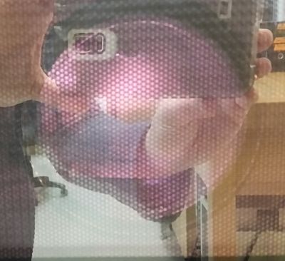
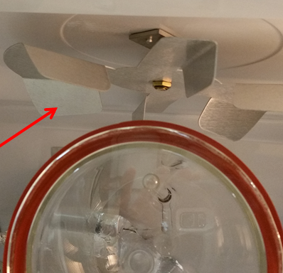
If you notice when using the Plasma Preen that you get plasma but it seems “locked” (i.e. you see a pink-purple glow but it is not moving) the problem could be that the antenna (fan at the top of the chamber) is no longer turning.

The fan may have stopped turning because the O-ring that is used to turn it has worn down and snapped. This protocol will explain how to take the Plasma Preen apart and replace the O-ring.


If you have pretty pink-purple plasma but it isn’t moving your antenna might not be rotating. “Locked” plasma won’t give you a good bond between PDMS and glass. Apologies for the reflection in the microwave door.
If the plasma is locked, it might be because this whirligig is not spinning.

Materials

You will need the following to change the brushes in the lab roller drums:

  • New O-Ring (#263 O-Ring)
  • Philips head screwdriver
  • Small flathead screwdriver
  • Pliers or wrench
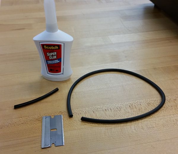
  • Super glue
  • Razor blade

Protocol

  • TURN OFF THE PLASMA PREEN AND UNPLUG EVERYTHING.
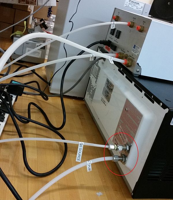
  • You are only going to be dealing with the “microwave” part of the plasma preen, so unhook the tubing at the body of the microwave (see picture). These should only be finger-tight, so you should not need a wrench.

Remove the tubes connected to the microwave body.

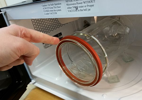
  • Remove the glass bell jar from inside of the Plasma Preen (don’t forget this costs >$800 to replace, so put it in an uber-safe spot). Once the bell jar is safe, maneuver the Plasma Preen to a clear workspace where you have plenty of room to get on all sides of it.

Slide the bell jar out carefully and put it in a safe location. Perhaps a giant box full of feathers. Really. Put it somewhere away from where you are working with padding so it won’t get broken!

  • Remove the black case of the microwave
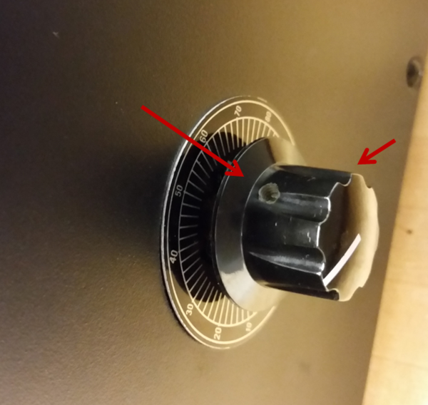
    • You will need to remove the handle to the analog power regulator (see picture). This can be done using a small flathead screwdriver and loosening the two screws. Then use the pliers or the appropriate wrench to remove the nut holding the potentiometer to the case.

The red arrows label the screws holding on the knob. One screw is hiding about a quarter turn from the one visible in the picture.

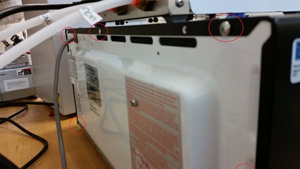
    • Remove the screws holding the case on. There are 5 screws on the back of the unit and one per each side (7 total, 5 silver, 2 black). There are 4 plastic brackets on top of the microwave that need to be removed. Place the screws and brackets in a beaker, or similar, so that you don’t lose them.

There are 5 screws on the back. One is hiding in the bottom corner. There are two screws on the sides. One is visible in the picture of the analog power regulator above.
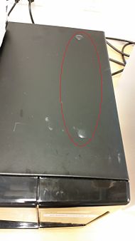
There are four brackets on the top. Here are two of them. They pop in and out.

    • Slide the case back and off. NOTE: The analog power regulator is a pain to deal with. You can gently push its shaft through the case to get the case off.
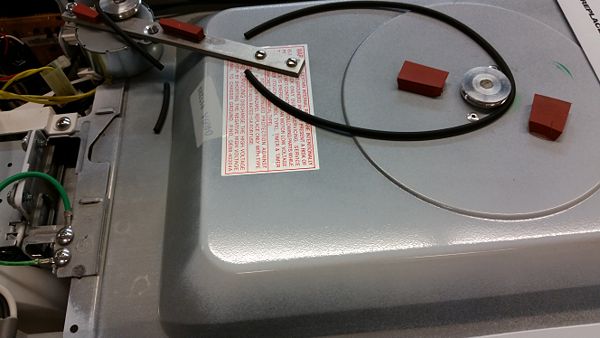
  • Check the O-ring. The O-ring is quite obvious and is right at the top of the machine. Check if it is broken or off of its pulleys. If broken, remove the broken pieces and throw them away.

In this case, as soon as the cover was removed it became obvious that the O-ring was broken.


  • Replace the pulley.
    • Take a #263 O-ring and cut it with a razor blade.
    • Wrap it around the pulleys and determine how long it needs to be. Note that it doesn’t have to be particularly tight as the antenna moves very easily. Cut the pulley with the razor blade so that when the ends are held together it is the right size.
    • Glue the two ends of the O-ring together with super glue. Allow to dry.
    • Place the O-ring around the pulleys.

O-ring arts and crafts. Cut to the desired length. Glue back together. Put over pulleys. Done.

  • Reassemble the plasma preen.
    • Start by maneuvering the potentiometer into position (get the shaft through the case). Secure it with the nut. Note that it is easiest to make sure it is in the fully off position, that way you know how to put the knob back on such that the white indicator line points at approximately the correct place (power range 0-100%).
    • Slide the case into place. There are brackets on the top and both sides. These will click into place. If the case isn’t fitting smoothly it is most likely because these are not appropriately aligned. Don’t force it. Just back up and try again taking careful note of where the brackets on the case are and how they should align with the body. Seriously don’t force it. It will happily slide into place if you line everything up correctly.
  • Reattach the tubing from the vacuum and the gas source to the back of the microwave.
  • Replace the bell jar.

Helpful Links

Notes

Please feel free to post comments, questions, or improvements to this protocol. Happy to have your input!

  1. List troubleshooting tips here.
  2. You can also link to FAQs/tips provided by other sources such as the manufacturer or other websites.
  3. Anecdotal observations that might be of use to others can also be posted here.


QX200 Digital Droplet PCR-PDF

Abstract

ddPCR is a method to quantify absolute copy numbers of a target.

Materials

Reagents

  • QX200 EvaGreen Digital PCR Supermix
  • QX200 Droplet Generation Oil
  • DG8 Cartridges
  • DG8 Gaskets

Equipment

  • QX200 Droplet Generator and Reader
  • 96 well PCR
  • 50 ul Multichannel, Rannin tip compatible.
  • Plate Sealer

Primer Design

Widely accepted quantitative PCR (qPCR) design guidelines apply to ddPCR primer design. Important criteria for single primers include melting temperature (Tm), length, base composition, and GC content. Ensure that paired primers do not exhibit significant complementarity between 3′ ends because this can result in primer-dimers.

  • Plan to amplify a 60–200 bp product
  • Avoid regions that have secondary structure when possible, the ΔG should be > –9.0 kcal/mole
  • Choose a region that, ideally, has a GC content of 40–60%
  • Strive for a Tm between 60 and 65°C. Ideally 62C. Probes should have a Tm 6C higher than the primers
  • Use Primer3 or BLAST-primer

Procedure for Evagreen DDPCR Reactions

Notes: Reactions must be multiples of 8. Use filter tips when possible.

1. Prepare dilutions of the samples. The dynamic range of the QX200 is 1-100,000 copies per 20ul reaction on a good day. Using a qubit, estimate the copy number of the target and prepare the dilution. Or if the samples are to dilute to measure, but similar in concentration, run the dilutions of a single sample to hone in on a dilution. Intact eukaryotic genomes should be ≤66 ng per 20 μl reaction. Otherwise, a restriction digest might be necessary.

2. Thaw supermix on ice. And vortex vigorously.

3. Optional. If the target is genomic DNA, over 66ng of input or a copy number assay, Digestion is recommended. Pick a restriction enzyme with a small cut size and low salt, that targets outside your amplicon.

4. Prepare reaction. It is critical to have exact volumes for accurate quantification. Thus the over preparation of the reaction mix. I recommend adding 2.25ul of sample in step 7, as it makes downstream calculations easy.

Component μl per 25μl sample μl for 8 25μl samples Final Conc
2X SuperMix 12.5 100 1x
Primers 100μM each 0.025 to 0.0625 0.2 to 0.5 100nM to 250nM
Restriction Enzyme ? ? 2-5 units
Sample (don’t add yet) ? ? 1-100k copies
H20 =12.5 – (Primer*2+RE+Samp) =100 – (Primer*2+RE+Samp)

5. Vortex the hell out of the reaction mix. And then vortex it some more. Spin briefly.

6. Dispense a volume that is equal to 22.5μl – Samp μl into locking PCR strip tubes.

7. Add your samples to the tubes.

8. Vortex the tubes at full speed till your hands go numb or the vortexer catches fire, whichever occurs first. Spin briefly.

9. Place a new DG8 cartridge in the holder. Using the Rainin p20 add 20ul of the samples in to the sample row, avoid bubbles, place the tips on the bottom corner of the well and tilt the pipette slightly, ~15°. Slowly dispense. Don’t go past the first stop. If for any reason you are unable to transfer exactly 20μl for a sample, take an amount you can and record it.

10. Place 70μl of Droplet Generation Oil for EvaGreen in the oil wells. Place a new red gasket over the hooks and place the assembly in the droplet generator. Press the button and wait. If for any reason the entire 20μl of sample is not consumed, measure the remaining amount and record it.

11. Using the Rainin L-50 with green box tips set to 40μl. Slowly place the tips into the bottom corner of the well at a 45° tilt. Slowly and smoothly draw the droplets, don’t aspirate air. Slowly deposit droplets into a column of a semi/unskirted heat sealable 96 well plate.

12. Carefully carry the plate to the heat sealer, and seal with a pierceable foil.

13. Carefully carry the plate to the PCR. And run the reaction as follows

Cycling Step Temperature,C Time Ramp Rate Number of Cycles
Enzyme Activation 95 5 Min 2C/sec 1
Denaturation 95 30 Sec 40
Annealing/Extension 60 1 Min 40
Signal Stabilization 4 5 Min 1
90 5 Min 1
Hold 4 Inf 1

14. After thermal cycling, place the sealed 96-well plate in the QX200 Droplet Reader.

Data Acquisition and Analysis

1. Open QuantaSoft TM Software to set up a new plate layout according to the experimental design.

2. Under Setup, double click on a well in the plate layout to open the Well Editor dialog box.

3. Designate the sample name, experiment type, QX200 ddPCR EvaGreen Supermix as the supermix type, target name, and target type: Ch1 for FAM.

4. Select Apply to load the wells and when finished, select OK.

5. Once the plate layout is complete, select Run to begin the droplet reading process. Select EvaGreen as the dye set used and run options when prompted.

6. After data acquisition, select samples in the well selector under Analyze. Examine the automatic thresholding applied to the 1-D amplitude data and, if necessary, set thresholds or clusters manually.

7. The concentration reported is copies/μl of a 20ul ddPCR reaction. If using 2.25ul of sample in step 7, the reported concentration is 1:10 dilution of the original.

Procedure for Probe DDPCR Reactions

Notes: Reactions must be multiples of 8. Use filter tips when possible.

1. Prepare dilutions of the samples. The dynamic range of the QX200 is 1-100,000 copies per 20ul reaction on a good day. Using a qubit, estimate the copy number of the target and prepare the dilution. Or if the samples are to dilute to measure, but similar in concentration, run the dilutions of a single sample to hone in on a dilution.

2. Thaw supermix on ice. And vortex vigorously.

3. Optional. If the target is genomic DNA, over 66ng of input or a copy number assay, Digestion is recommended. Pick a restriction enzyme with a small cut size and low salt, that targets outside your amplicon.

4. Prepare reaction. It is critical to have exact volumes for accurate quantification. Thus the over preparation of the reaction mix. I recommend adding 2.25ul of sample in step 7, as it makes downstream calculations easy.

Component μl per 25μl sample μl for 8 25μl samples Final Conc
2X SuperMix 12.5 100 1x
Primers 100μM each 0.225 1.8 900nM
Probes 100μM each 0.0625 0.5 250nM
Restriction Enzyme ? ? 2-5 units
Sample (don’t add yet) ? ? 1-100k copies
H20 =12.5 – (Primer*?+Probe*?+RE+Samp) =100 – (Primer*?+Probe*?+RE+Samp)

5. Vortex the hell out of the reaction mix. And then vortex it some more. Spin briefly.

6. Dispense a volume that is equal to 22.5μl – Samp μl into locking PCR strip tubes.

7. Add your samples to the tubes.

8. Vortex the tubes at full speed till your hands go numb or the vortexer catches fire, whichever occurs first. Spin briefly.

9. Place a new DG8 cartridge in the holder. Using the Rainin p20 add 20ul of the samples in to the sample row, avoid bubbles, place the tips on the bottom corner of the well and tilt the pipette slightly, ~15°. Slowly dispense. Don’t go past the first stop. If for any reason you are unable to transfer exactly 20μl for a sample, take an amount you can and record it.

10. Place 70μl of Droplet Generation Oil for probes in the oil wells. Place a new red gasket over the hooks and place the assembly in the droplet generator. Press the button and wait. If for any reason the entire 20μl of sample is not consumed, measure the remaining amount and record it.

11. Using the Rainin L-50 with green box tips set to 40μl. Slowly place the tips into the bottom corner of the well at a 45° tilt. Slowly and smoothly draw the droplets, don’t aspirate air. Slowly deposit droplets into a column of a semi/unskirted heat sealable 96 well plate.

12. Carefully carry the plate to the heat sealer, and seal with a pierceable foil.

13. Carefully carry the plate to the PCR. And run the reaction as follows

Cycling Step Temperature,C Time Ramp Rate Number of Cycles
Enzyme Activation 95 5 Min 2C/sec 1
Denaturation 94 30 Sec 40
Annealing/Extension 60 1 Min 40
Signal Stabilization 4 5 Min 1
90 5 Min 1
Hold 4 Inf 1

14. After thermal cycling, place the sealed 96-well plate in the QX200 Droplet Reader.

Data Acquisition and Analysis

1. Open QuantaSoft TM Software to set up a new plate layout according to the experimental design.

2. Under Setup, double click on a well in the plate layout to open the Well Editor dialog box.

3. Designate the sample name, experiment type, ddPCR Supermix for Probes as the supermix type, target name, and target type: Ch1 for FAM. Ch2 for HEX/VIC

5. Select Apply to load the wells and when finished, select OK.

6. Once the plate layout is complete, select Run to begin the droplet reading process. Select the appropriate dye set used and run options when prompted.

7. After data acquisition, select samples in the well selector under Analyze. Examine the automatic thresholding applied to the 1-D/2-D amplitude data and, if necessary, set thresholds or clusters manually.

8. The concentration reported is copies/μl of a 20ul ddPCR reaction. If using 2.25ul of sample in step 7, the reported concentration is 1:10 dilution of the original.
McClean: Designing “Yeast Toolkit” compatible primers-PDF

Overview

This protocol is written to prepare the user to design PCR primers such that the end product will have BsaI and BsmBI cut sites, as well as the correct flanking overhangs. It is intended to supplement both Lee, M. E., DeLoache, W. C., Cervantes, B. & Dueber, J. E. A Highly Characterized Yeast Toolkit for Modular, Multipart Assembly. ACS Synthetic Biology at <http://pubs.acs.org/doi/pdf/10.1021/sb500366v> (2015) and its own supplementary information.

Materials

  • NCBI Primer-Blast (or other primer design tool)
  • Basic understanding of Golden Gate Assembly (search for an overview in other websites if link doesn’t work)
  • An understanding of what DNA sequences BsaI and BsmBI recognize and where they cut.

Protocol

  1. Design primers as normal, such that they can be used to PCR amplify your gene of interest. NCBI’s Primer-Blast tool is handy for this. See McClean: designing primers for more help.
  2. Prefix the 5′ end of your forward primer with GCATCGTCTCATCGGTCTCANNNN
  3. Prefix the 5′ end of your reverse primer with ATGCCGTCTCAGGTCTCANNNN
  4. The desired end product will be this, where NNNN is the type specific overhang and can be found in the paper’s SI.
  • Forward primer —>
  • 5′- GCATCGTCTCATCGGTCTCANNNN- gene of interest – NNNNTGAGACCTGAGACGGCAT -3′
  • 3′- CGTAGCAGAGTAGCCAGAGTNNNN- gene of interest – NNNNACTCTGGACTCTGCCGTA -5′
  • . . . . . . . . . . . . . . . . . . . . . . . . . . . . . . . . . . . . . . . . . . . . . . . . . . . . . . . . <— Reverse Primer

Notes

Please feel free to post comments, questions, or improvements to this protocol. Happy to have your input!

  1. List troubleshooting tips here.
  2. You can also link to FAQs/tips provided by other sources such as the manufacturer or other websites.
  3. Anecdotal observations that might be of use to others can also be posted here.

References

Lee, M. E., DeLoache, W. C., Cervantes, B. & Dueber, J. E. A Highly Characterized Yeast Toolkit for Modular, Multipart Assembly. ACS Synthetic Biology at <http://pubs.acs.org/doi/pdf/10.1021/sb500366v> (2015)


In vitro transcription-S2-PDF

Purpose

In vitro transcription using Escherichia coli RNA polymerase.

Materials

  • E. coli RNA Polymerase Sigma-Saturated Holoenzyme from Epicentre – (protocol)
  • Linearized template DNA
  • NTPs
  • DTT

Procedure

Prepare template DNA

  1. Generate linearized template via PCR. Do a 100 μL reaction using VF2 and VR.
    • Can be done once, frozen and reused.

Option 1: Preincubate repressor and DNA

  1. Mix
    • 20 μL repressor
    • 2 μL of PCR template
      • Do the same for relevant controls.
  2. Incubate 2 hours on benchtop.
  3. Make up 50 μL reaction
    • 22 μL repressor-DNA mixture
    • 10 μL 5X E. coli RNA polymerase transcription buffer
    • 0.5 μL of 500 mM TCEP since DTT chelates zinc
    • 10 μL of 2.5 mM each NTP
    • 5 μL RNase free H2O
    • 2.5 μL E. coli RNA polymerase holoenzyme
  4. Incubate at 37°C for 1 hr.

Option 2: Set up transcription reaction

  1. Make up 50 μL reaction
    • 25 μL RNase free H2O
    • 10 μL 5X E. coli RNA polymerase transcription buffer
    • 0.5 μL of 500 mM TCEP (since DTT chelates zinc)
    • 10 μL of 2.5 mM each NTP
    • 2 μL of PCR template <-perhaps cut this down? DNA is a pretty bright band?
    • 2.5 μL E. coli RNA polymerase holoenzyme
  2. Incubate at 37°C for 1 hr.

DNase treatment (optional)

This step hasn’t been tried.

An optional step is to treat the reaction with RNase free DNaseI to remove the template DNA.

  1. Add 6 μL DNaseI buffer
  2. Add 3 μL H2O
  3. Add 1μL DNaseI
  4. Incubate 1 hr at 37°C
  5. Heat inactivate for 10 mins at 75°C

Notes

  • EDTA should be added to a final concentration of 5 mM to protect RNA from being degraded during enzyme inactivation. But EDTA can chelate magnesium which is needed for DNaseI activity. So the EDTA may need to be added just prior to inactivation.
  • DNase I is not active on DNA bound to proteins.
  • DTT which is typically included in in vitro transcription reactions can chelate zinc. Therefore, replace DTT with TCEP when the presence of zinc is necessary.

Analyze transcription products

Then analyze via native agarose gel electrophoresis.

Controls

There are a few controls that can help to ascertain that the assay is working properly.

  1. Template without RNAP
    • To see what just the DNA template looks like when run on a gel.
  2. Template with RNAP
    • To ensure that the linearized template is transcribed by RNAP.
  3. Template with RNAP and the buffer that the repressor is resuspended in
    • To verify that any repression seen is not due to altered salt or pH conditions.

Notes

  1. If using either plasmid DNA or DNA template has been linearized by restriction enzyme digestion, Ambion recommends a Proteinase K treatment followed by a phenol:chloroform extraction to eliminate all traces of RNase prior to subsequent reactions. This treatment is necessary because most plasmid DNA has been subjected to RNaseA during purification and restriction enzymes may be contaminated with RNases.
  2. However, in the case of PCR generated templates, Ambion adds amplified DNA directly to the transcription reaction with no purification. 5 μl of a 100 μl PCR reaction (or about 0.05 – 0.2 μg of double-stranded DNA) is used as template. However, with shorter templates or low yields, the concentration of template in a 5 μl aliquot of the crude PCR reaction may be suboptimal. In that case, it may be desirable to concentrate the PCR product by alcohol precipitation. We do not generally find it necessary to phenol/chloroform extract the PCR reaction before precipitation, although in some cases it may be advisable to do so.