Overview
Working with blue light constructs (our CRY2 and CIB1- based induction system) requires working knowledge in yeast genetics and plasmid construction, simple electronics, and programming (in the Arduino environment.)
Plasmid & Strain Considerations
Generally, our CIB1 constructs are in plasmid backbones that are LEU2+, our CRY2 constructs are in those that are TRP1+, and our reporter constructs are in those that are URA3+. Thus, if following this convention, you must be using a strain that is prototrophic for these (i.e. LEU2, TRP1, and URA3 deficient.) We generally use either one of two strains for these purposes, yMM1146 or yMM1204. Most of our blue light plasmids are constructed with the pRS41(x) vectors (Sikorski and Hieter, 1989.) These are in our collection as pMM5-8. Note that these are the CEN/ARS (read: single copy) plasmids.
Setting Up an LED Array for Testing
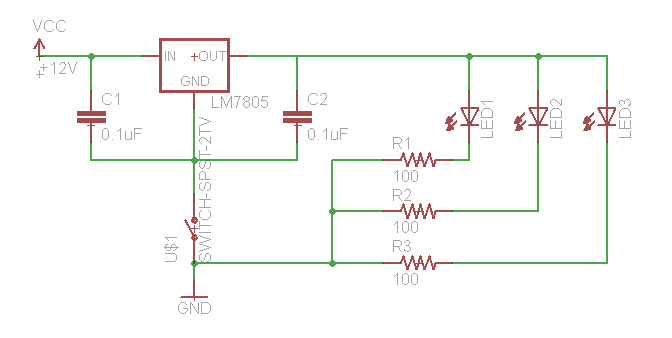
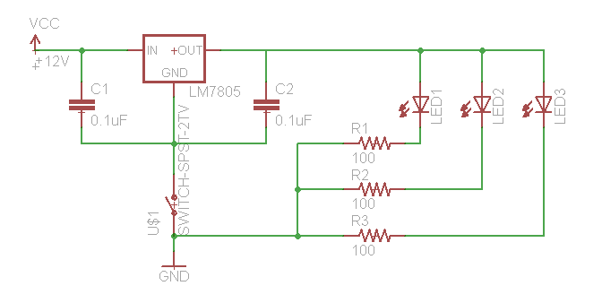
If you need to test your constructs to see if they “work,” this is best performed in batch on a roller drum. Arrange three LED’s (460 nm emittance for these constructs) at the 3, 9, and 12 o’clock positions of the roller drum so that they face the side of the drum (where they will be able to shine directly on culture tubes. Hook up the LED’s as follows: 
We use a 12V wall-wart with a 2.1 mm plug.
Take an overnight culture of your cells, grown in SC -Leu-Trp-Ura, and use it to innoculate a 1:50 subculture in SC -Leu-Trp-Ura in a foil-wrapped tube as to exclude ambient light. Grow it at 30°C for 5 hours. Take this culture and aliquot about half of it into a new, clear culture tube. Place both sets of tubes on the outer lane of the roller drum at room temperature and turn the LEDs on. When sampling, take from 100 to 800 μL of culture and add it to an equal volume of cold PBS + 0.1% Tween and hold this solution at 4°C until ready to run at the FACS facility.
Modifying the LED Array to Vary Light Pulses
You may want to vary the blue light exposure time for your cultures. We will use an Arduino microcontroller to control the switching. Use the Arduino IDE to upload the code:
//set pin that led is hooked up to int LEDPin = 6;
void setup() { //define LEDPin as an output
pinMode(LEDPin, OUTPUT);
}
void loop() { //enter time units in milliseconds
ledControl(3000, 3000);
}
void ledControl(int timeOn, int timeOff) {
 //turn led on, wait, turn led off, wait
 digitalWrite(LEDPin, HIGH);
 delay(timeOn);
 digitalWrite(ledPin, LOW);
 delay(timeOff);
}
Remember that times are in milliseconds. Keep in mind that this code is very simple and uses the delay() function, which will need to be modified if you need to add additional functionality to this program.
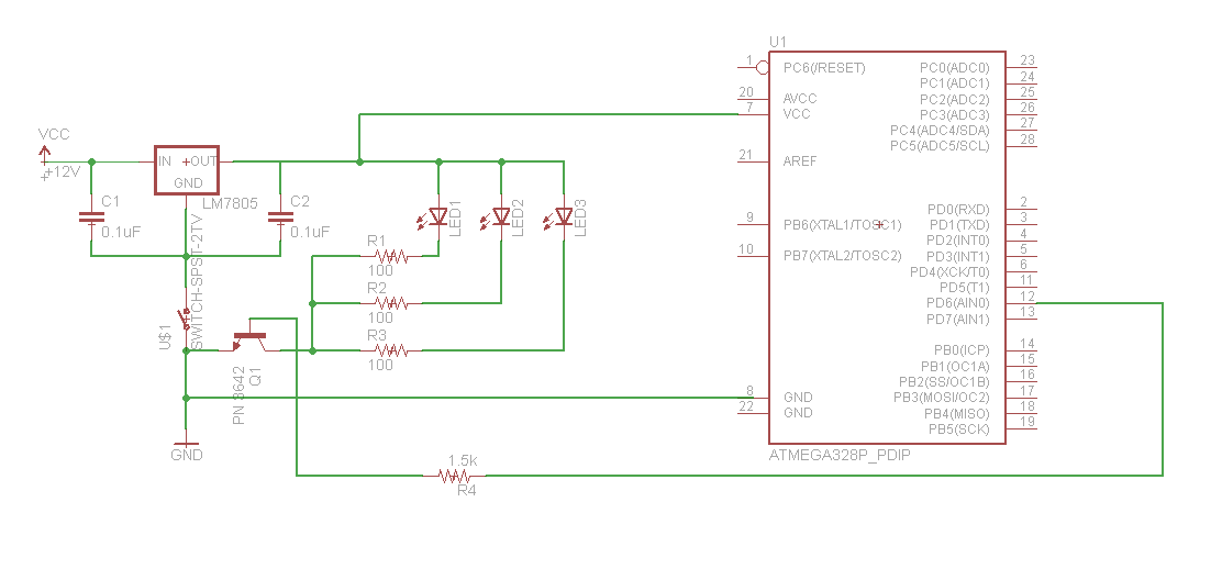
Hook up your LED array to the microcontroller as follows:

We have some extra PN 3642 transistors, or you should be able to get some in the Physics Stockroom.
Parts List
You can find these in the physics stockroom: 0.1 uF capacitors Bin #101065; 100 ohm 1/4 watt resistor #105917 (bin # not critical as long as it’s 100 ohm); 1.5 K ohm (or close to that) 1/4 watt resistor (not sure of the bin # but it’ll be by the other resistor in cabinet 10); 22 gauge solid core wire, gonna need a lot of it so get like 10 ft each of red and black; toggle switch, maybe like in bin #108170; 2N3642 transistor, Bin #108482 in cabinet 9 drawer 4;
Get these from Newark through Princeton Marketplace: Arduino: Newark part #63W3545; lm7805: #09J6572; 12V power supply #40P7518; breadboard #99W1760;
Get from sparkfun.com: barrel jack PRT-10811; LED’s(3): COM-08718 ;
References
Gietz, R.D. and R.A. Woods. (2002) TRANSFORMATION OF YEAST BY THE Liac/SS CARRIER DNA/PEG METHOD. Methods in Enzymology 350: 87-96.
Sikorski, R.S. and Hieter, P. (1989) A system of shuttle vectors and yeast host strains designed for efficient manipulation of DNA in Saccharomyces cerevisiae. Genetics 122(1): 19-27.


